
What is the Purpose of Minimum Flow?
Randal FermanOver the years use of the term “minimum flow” has evolved. Decades ago industrial centrifugal pump manufacturers quoted a single, relatively low value for minimum flow intended to prevent users from running their pumps to destruction. The term “minimum flow” generally meant the lowest continuous flow the pump was permitted to operate, without reference to duration, vibration level or other criteria. Today we have minimum flow values for continuous operation, for intermittent operation and for permissible temperature rise.

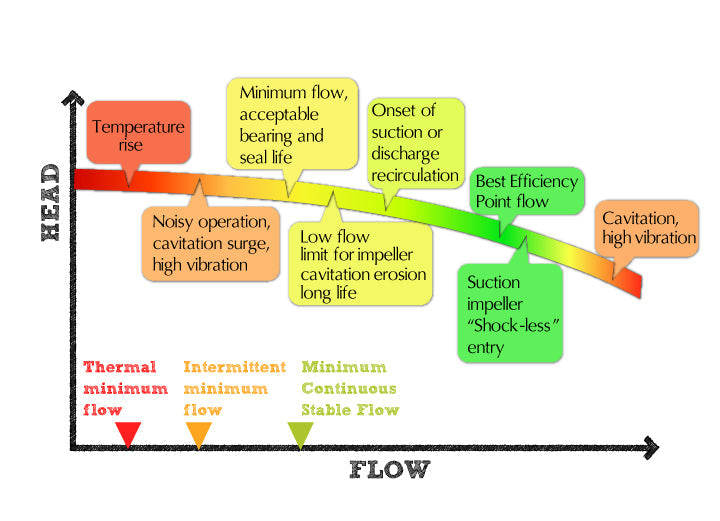
The accompanying chart Pump phenomena and minimum flows shows the relationships among the various off-design pump phenomena and minimum flow conditions. The head versus rate of flow curve with indicated phenomena is a variation of S. Gopalakrishnan’s from his well-cited paper titled, “A New Method for Computing Minimum Flow,” Proceedings of the Fifth International Pump Users Symposium; Texas A&M University, May 1988, pp. 41-47. As an aside, I recall Gopal (everyone knew him by that name) had made a local technical presentation using the now well-known chart, before it was published. Evidently the chart was copied from a handout of the overhead slides and was quickly pirated by another, and then others. Copies or variants of this chart are now found widely in papers and presentations on pumps.
The quoted minimum flow for continuous operation is usually called “Minimum Continuous Stable Flow” or its more common abbreviation “MCSF.” It is the flow below which the pump should not be operated continuously. The usual purpose of MCSF is to achieve satisfactory bearing and seal life; however MCSF may be based on other considerations. Any of the following factors may be considered in establishing the MCSF:
- manufacturer’s experience
- rule of thumb
- calculated onset of suction recirculation or discharge recirculation
- radial thrust
- temperature rise
- cavitation erosion intensity
- maximum permissible pressure rise (for system purposes)
- maximum permissible power rise (high specific speed and axial flow pumps)
- a combination of the above factors or others not listed
For hydrocarbon process industry API 610 specification pumps, the value of MCSF is normally coincident with the lower flow limit of the “Acceptable Operating Range” (refer to chart titled “Vibration limits for Allowable Operating Range and Preferred Operating Range”) where a specified vibration limit is not to be exceeded.

MCSF is a value that can range from roughly 10% to 80% of Best Efficiency Point flow depending on pump size and type, operating speed, impeller suction geometry, liquid density, and other factors. A size 2” (50mm) discharge single-stage process pump may have an MCSF as low as 10% of BEP flow. MCSF is often in the range of 30% to 60% of BEP flow for process pumps with discharge sizes 3” (75 mm) and larger. Large mixed flow vertical pumps and very high head-per-stage centrifugal pumps may have an MCSF greater than 60% of BEP flow. Axial flow pumps have a power curve that rises toward shutoff and minimum flow may be limited by the power rating of its driver.
On certain high energy pumps the minimum flow is governed by cavitation erosion damage. Minimum continuous flow for 40,000-hour impeller erosion life is where the system NPSH Available curve intersects the pump’s NPSH Required curve, at lower-than-BEP flow.
Intermittent minimum flow, when specified, is usually given as a percentage of MCSF. On some applications the governing value may be based on temperature rise. On large high energy pumps the value of intermittent minimum flow could be, for example, “70% of MCSF and not to exceed 100 hours per year.”
For some applications a thermal minimum flow or “Minimum Continuous Thermal Flow” is specified based on permissible liquid temperature rise. MCTF is usually, but not necessarily, lower than MCSF. While a pump thermal minimum flow is not always specified, the end user can readily calculate its value based on input mechanical power heating up the liquid. The limiting temperature rise is based on a safe margin to prevent flashing of the pumped liquid to vapor, potentially causing pump seizure.
Thermal minimum flow is not normally a concern at pump start-up as long as the closed discharge valve is set to begin opening right away. If the margin of system NPSHA above pump NPSHR is minimal, then the temperature rise conditions at pump start-up should be checked carefully.
A few pump applications, such as a vertical turbine jockey pump for maintaining pressure in a large fire sprinkler system, can potentially operate continuously at shutoff while pump suction recirculation mixes with the water in the sump in which it operates. The sump acts as a heat sink and a minimal water temperature rise is not a problem. This example is a rare exception to an almost invariable stricture on operating the pump continuously at shutoff.
The purpose of minimum flow is generally to prevent undue wear and tear or damage to the pump. In the real environment of a process or utility plant, a pump is operated at just about any condition demanded by the situation at hand. Thus there are different pump minimum flows for different purposes.
For an independent evaluation of a pump minimum flow issue, contact an experienced consulting engineer who can help with your specific application. Please take a look at our services to see our areas of expertise.
52 comments
Appreciate if someone in this forum can clarify what happen if in case of failure of a centrifugal multi stage HP BFW pump minimum flow recycle valve and possibility of overpressuring the suction pressure if the minimum flow line is directly connected to the suction of the pump. the below is the system description.
the system consists of a series of 3 LP BFW pumps which are feeding to 3 HP BFW pumps with common suction and discharge header.
the LP pumps discharge are rated for 300# and HP Pumps for 1500# pressure rating. the LP pumps have individual minimum flow recycle back to the suction vessel which is atmospheric BFW tank . the HP pumps minimum flow recycle lines are connected directly to the HP pumps common suction header which is common Discharge header of LP pumps via a cooler which can cool down the minimum flow before it is recycled back to the HP pump suction (so no overheating issue). the dischrge head of LP pumps are 320 m and for HP pumps it is 900 m at their rated flow 130 m3/hr each (normally two pumps running and one in stand-by).
so the question is if the minimum flow recycle valve of one HP pump fails to fully open then what would happen to the suction pressure of that HP pump if only one sets of LP/HP pumps running and same question if two set of LP/HP pumps running.
the question is raised due to consideration of 300# rating of LP discharge header which is connected to 1500# rating of the suction and discharge of HP pumps and to evluate if there is a need for PSV for this case or not.
appreciate your feedback on this.
regards,
Matt
Dear Moe,
You are correct – pump minimum flow can always serve a process or safety function. In either case, the requirements and limitations of both the pump and the system must be considered.
Thank you for the comment,
Randal
Minimum flow pumps help protect the pump if the downstream unit is plugged or under any circumstances went down or tripped. On the other hand, the base of every column has a level set point it helps maintaining the level set point not to run out of level which has a high possibility of effecting the on a column distillation to malfunction and also the heating media will rupture the tubes of the re-boiler.
Please comment back if I was mistaken
Alan,
For reference, I assume you’ve looked at my reply to Jaqueline on 27 November 2013. Calculate the temperature rise of the pump for several low flow conditions. At these low flow conditions adjust the NPSHR upward as necessary to compensate for the temperature rise of the balance leakage. Remember, the return leakage flow is not permitted to flash to vapor as it returns to the reduced pressure suction area. The pump manufacturer’s NPSHR curve may already reflect this requirement. The MCTF condition is established based on having sufficient NPSH margin to prevent flashing.
I hope this helps.
Randal
Dear Randal,
How to calculate minimum continuous thermal flow ?