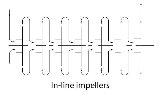
Multi-stage pump in-line (tandem) versus opposed impeller arrangements
Randal FermanCommon to early twentieth century multi-stage rotodynamic (centrifugal) pumps were design features for minimizing axial thrust. At that time the thrust bearings available had limited load carrying capability. Design solutions evolved in two principal directions. One design approach was to hydraulically balance the thrust for each stage or for the entire series of in-line (tandem) impellers utilizing close radial or axial running clearances in rings, drums, discs, or combinations of those and sometimes in combination with balance holes or openings in the impeller back shroud. The other design approach was to pair single suction impellers in an opposed impeller (usually back-to-back) arrangement, or utilize double suction impellers in series. With either of these principal approaches, a thrust bearing was still required to carry some residual unbalanced thrust and to cope with transient axial thrust events.


Thrust bearing and thrust compensating devices have evolved considerably in the last hundred years, enabling a much wider range of thrust load carrying capacities and operating speeds. Today the majority of multi-stage pump offerings employ in-line impeller arrangements. These designs are inherently less complex and less expensive to manufacture.
Some users prefer an opposed impeller pump arrangement that substantially reduces the residual unbalanced thrust. This is a consideration for applications that can experience frequent or severe system transients such as load cycling power plants. In a between-bearing multi-stage pump a pressure breakdown bushing is still necessary to reduce the seal box pressure and a thrust bearing is still required to carry the residual unbalanced thrust.
API 610 for oil and gas production and HPI does not permit an axial clearance for balancing thrust, effectively excluding disc-type balancing devices. This tends to favor opposed impeller designs for some API 610 applications.
For a given number of stages, an in-line impeller arrangement will have a shorter span between bearings. The opposed impeller arrangement requires a larger diameter shaft to obtain the equivalent maximum shaft deflection. But there are practical design constraints to increasing the pump shaft diameter, so the between-bearings in-line arrangement will have a design edge in some abrasive service or very low density (low lubricity) applications.
A few high speed, high head designs take advantage of the opposed impeller arrangement for purposes of increased rotordynamic stiffness from the center bushing which separates the opposed stages.
For most applications, pump manufacturers are capable of offering either in-line or opposed impeller designs for a given application and a few companies can offer both. The purchaser, of course, should request from the manufacturer a user list providing evidence of successful application experience with the impeller and thrust bearing arrangements offered.
